Introducing a Donald Engineering custom Manifold Assembly: Precision engineering at its best!
 When it comes to precision control and performance, our custom manifold assembly stands tall. Crafted with precision and engineered to perfection, this assembly is here to take your projects to new heights.
Our customer needed to fill a vessel to a precise amount of pressure and then isolate the controlling valves from the vessel as the vessel did its operations. (In some cases it could be chemical reactions, be heated from external sources or both). Once the vessel’s operation concluded, it would return to a lower pressure state and other functions could be initiated.
We solved this by helping design and then manufacture a custom integrated block.
Here are the specifications and some key features:
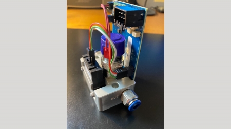
- Custom Anodized Aluminum Manifold: Compact yet powerful measuring 4.375” wide x 3” tall x 1.5” deep
- Clippard cordis regulator:
- Precision control with a range of 0-150psi and .25in3 / 2.7 L/min flow rate.
- Housed with an internal sensor
- 3.3V Serial
- 1/8” NPT Ports
- Clippard isolation valve
- Built to last with a normally closed setup
- Terminal pin connection
- Capable of handling pressures up to 500psi at 12L/min flow rate.
- Manual dump valve
- Pressure Transducer
- Providing accurate pressure readings from 0-300psi
- 4-20mA output
- ¼ NPT male connection
The primary Clippard components we are using are the
Cordis proportional pressure control and a
high pressure EV valve ensure top-notch performance and reliability.
This manifold assembly uses a standard cordis proportional pressure controller. Clippard offers various options including high pressure, remote sensing, and proportional flow control.
Discover more about Clippard options here.
Our team specializes in low-quantity special projects; this manifold assembly is a perfect example.
Ready to see how it can transform your application?
Contact us today to schedule a consultation!
Adding Significant Value with Hydraulics
In this addition of the Donald Engineering Pilot House, our focus is going to be on Hydraulics. If Hydraulics doesn’t typically hold your attention, I would like to encourage you to take a read anyway. We will be focusing on how one manufacturer has approached a mature technology by doing things differently and adding significant value. The technological add to each of these things we are going to highlight is something many of us can learn from and apply in our own individual fields of expertise.
When we go to market to solve a customer’s problem, we have “tools” in our “toolbox” that are the starting points for each solution. These tools are products, but also design features and philosophies. Each tool or philosophy has weaknesses and strengths. Why we may select one over the other is based on the customer’s needs and experiences. We often think of these negative experiences as “pain points”.
For partial example:
Pneumatic solutions typically have a lower cost to purchase, marginal motion control, and a very high cost of ownership as they are inherently very inefficient.
Hydraulic solutions are moderate costs to purchase, potentially applying the highest forces versus packaged size (smaller components to generate tonnage) much more efficient than compressed air, but are noisy and often leak.
Ball Screw / Roller Screw driven by servo have great control, quite but are the highest cost to purchase (but this is improving every year) most energy efficient, and more complex to troubleshoot (takes a laptop).
So, back to Hydraulics, they have been around and utilized for centuries. First as water flowing (water wheel) then steam applications and finally as we understand them today. The physics of energy transfer through pumped fluids is well understood. They can transmit and apply the most energy of the 3 disciplines mentioned with great control. However, not everybody likes or needs Hydraulics. To make them more appealing, Continental Hydraulics continues to innovate to make this mature product more desirable and successful. Here are some value examples:
- 100% tested, high-quality products. Continental’s warranty costs are .02% of sales. This means that for every $10,000.00 of product sold, they warranty $2.00!
- They offer a 3-year warranty!
The quality is realized not in warranty dollars, but rather your lack of downtime due to quality issues! (Just think about what that is worth over a year).

- The VS6M and NG10 family of D03 and D05 valves have all external surfaces Zinc-Nickle plated. (Think of the corrosion resistance in humidity, wash down or mobile applications)

- The NG10 family of D05 valves are manufactured with D03 sized coils.
- Lower Costs of components and commonality of spare parts
- Reduced current and lower electrical operating costs!
- Lower flow than full-size D05 coil. 33 gpm vs 38 (who operates a D05 above 25 gpm anyway? Only someone who has no consideration for heat gain and energy loss due to pressure drop…)

- MGL and MJL families of low-profile proportional valves
- Horizontally mounted on-board amplifier PCB.
- Less space
- Super high vibration resistance due to a lower center of gravity. (70+G force capable!)
- M12 5 pin wiring
- Lower cost of cabling vs. 7 pin military connector that is standard on most proportional product
- Lower cost to manufacture / lower price point to the customer
The next example of extreme excellence is our product highlight for this edition. The MX (and MK) series of proportional valves.
 Servo-proportional directional valves are one of the keys to great closed-loop hydraulic motion. Every manufacturer has their “flagship valve” that they like to offer as the “must have” valve for great position control, pressure / force or velocity control.
The MX series offers unequalled performance compared to other manufacturers, and even more value when you consider the price point. In doing some deep research, we have found that there are 2 valve manufacturers with greater performance. Both valves are voice coil driven – which has its own inherent negative issues – as well as greater costs.
How did Continental provide this exceptional value to this incredible valve? By thinking practically versus academically. The industry designs valves for speed and accuracy and all measure against the same criteria. This criteria is revealing, but is not representative of real world use.
- To classify performance the spool in the valve is subjected to a series of rapid commands. These commands are typically:
- Step Response 0-100% full shift
- Cyclical Continuous full shift = Full shift A – full shift B (think sine wave)
- Cyclical Continuous small shift = 5 or 10% shift A – 5 or 10 shift B
Because nothing is instant, there is a delay in command versus reaction. How the coils are energized, de-energized, internal error correction algorithms and inertia + flow forces on the spool all contribute to reaction time and describe the valve performance.
- The industry utilizes 90 degree phase lag to describe how behind the spool is versus the sinusoidal command.
- Amplitude describes the percentage of actual spool shift versus commanded shift (100% move or 5% move) and -3dB amplitude is the criteria for measured inability to attain target
However these criteria don’t represent real world scenarios. If your valve is 90 degrees out of phase, your actuator is way behind because it is lagging even further behind the valve and your scenario is pretty much failing or out of control / unstable
Continental engineers asked the common sense question – how much phase lag is more real world and represents a better control scenario? They settled on creating their tuning algorithms to be maximized at 30 deg phase lag. As a result, they came up with a substantially faster valve than the competitors. It is faster in the small incremental movements which better represent real-world applications.
All these performance criteria are measured on a graph called a Bode Plot.
Real-world control drives us to look at the small movement criteria of a 5 or 10% move,
How fast can we make small corrections and how much delay is realized? (the more “small corrections” you can make per second = accuracy!)
Following is a comparison of results found in the manufacturer’s literature.
 The chart to the left is the latest data – to the best we could find.
(Click chart to enlarge).
 The MK series of proportional valves are lower cost and lesser performance; however, the internal algorithms were developed with the 30-degree phase lag optimization. The MK is a proportional spool in a conventional body, different than the MX which has a linear cut spool and machined sleeve design. The MK also has a double solenoid with a center no flow “null” design (1.5 to 2% overlap). The Null or deadband characteristic is typically not as advantageous as a zero null valve. But depending on the application, it may present no disadvantage. The VED03MK with 3 times faster “crossing delay” as compared to other manufacture valves of this design, may just be the economical performance you’ve been looking for.
Our team is prepared to help you with your unique application. Please Contact your DE Technical Sales Representative to get started!
A Tale of the Air Dryer
 One of our customers recently gave us an excellent example of a gift that keeps on giving and as a result encountered some undesired down time and expense. This tale is about one of their compressed air systems and the failure of the air dryer on a hot and humid stretch of weather. The weather forecasters say the hot and humid weather is over, but unfortunately, the issues will continue to nag for weeks to come.
Compressed air systems are one of the central systems that make factories go. The systems and concepts of how they work are not overly complex, but require consistent and careful attention to stay operating correctly.
First, we would like to give an overview of a compressed air system (see us for a schematic and details of how to build a proper system) and then discuss what issues the failure of the dryer caused and finally the remedies.
Compressed air systems start with an air compressor. The air compressor sucks in ambient air and packs (compresses) it. With this ambient air, the relative humidity comes along. When it is warm outside, the air is expanded and there is room for more water vapor to reside in the air. When air is compressed there is a significant amount of friction in the air and the outlet of the compressor is extremely hot. (Air compressors have something like 50% of input energy put into heat. Yikes, not super-efficient…). The compressed air goes into a large “wet receiver” tank. In this tank the air begins to cool and some of the moisture condenses out and collects in the bottom of the tank.
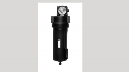 From the “wet tank” the air goes through a dryer. There are various types, (refrigerant, desiccant etc) but all work to remove moisture from the air and lower the dew point (temperature at which the moisture precipitates out of the air) down to an acceptable level. The “dry” air is now stored in a “dry receiver” tank. (Pictured is a high water removal filter). The purpose of the tanks are to smooth out or buffer the demands of the plant from the compressor and dryer – allowing the compressor to be more efficient. Typically, at the compressor there are filters, which help remove some oils and water vapors.
Trouble begins when the dryer fails due to some issue, or when it is overwhelmed because it is running at max capacity and can’t keep up with the extra humid air found in a heat wave. When the dryer doesn’t keep up, wet air goes into the dry tank, overwhelms the filtration and ventures into the distribution piping. Typically, when compressed air leaves the dry tank it is distributed around the plant through a “Halo” - a pipe system at the ceiling that loops back to itself. From the Halo air drops bring air to the individual points of use as needed.
Here is the second trouble spot. Many of these piping systems are made from black pipe a.k.a. steel. (Other forms of pipe are used sometimes, but all have issues the least issues occur with aluminum piping, see us for details.) The pipes oxidize (rust) and the oxidation breaks free and flows into the air filters and regulators at the point of use. Once these filters get overwhelmed or saturated, contaminated air enters the machine valves and the machine starts to have cycle failures due to contamination.
After ~ 12 years of good operation, the customer had two failures in the last 14 months. One during each summer hot spell.
The photos show the rust collected out of 1 ea. 1” npt 5 micron filter. This filter was installed just prior to the dryer failure and operational for only 4 weeks.
 To remedy the situation, the customer is replacing filter elements monthly – until the debris volume goes down.
The customer has installed 5 micron filters at the Halo, then also filters – 5 micron + .3 micron at ground level at the machine.
We have also supplied 1 ¼” and 1 ½” high volume water separators at various points around the halo system.
 Unfortunately, this customer isn’t unique. We are called in to help customers around West Michigan each and every summer with water and filtration issues as a result of dryer hiccups.
This shows the importance of a properly executed air prep system with the proper drip leg and air filtration.
If you want to prevent an air dryer failure let us configure the best air entry safety solution for your system. Contact our team today!
The Spike Relief Solution
This month our application story centers on the success of the spike relief valve featured in our product high-light.
Our customer is a pallet manufacturer that processes from cut log to finished pallet. He starts by loading logs into his lumber mill though a singulator / feeder. Check out the outdoor photo of the lift into the building, it gives an idea of how the logs were causing trouble.
 The “stairs” oscillate angularly to separate the logs and present them one at a time into the infeed conveyor inside the building.
The customer was experiencing premature pump failure and it was diagnosed by our sales representative to be caused by intermittent spikes that occurred as logs rolled back down the incline as they separated themselves. The down time was costly and frustrating as pump failure was approximately every 6 months.
(In this case the pump was a vane pump. A piston pump may have survived a little longer, but it too may become problematic over time as the spike lifts the shoes and causes increased case pressure. Likely causing the shaft seal to leak and then later damaged shoes would destroy the swash plate.)
In the following photo you can see the crack / split in the pressure ring at the 9 o’clock position in the ring.
 Per the salesman’s recommendation, the customer installed an Oilgear Spike relief valve at the pump and began trimming his spikes. The customer has been running trouble free since.
Adding the Spike Relief Valve onto a Oilgear Pump delivers rapid pressure relief for total system protection. Investing in a spike relief valve saved the customer time and money, lowering the total cost of ownership.
The smallest of issues can create havoc in machinery and business operations. It is essential to be proactive in finding solutions to these problems. The Donald Engineering team is trained to assess your unique application problem and provide the best possible solution.
If you are facing an interesting equipment challenge, there might be a simple solution around the corner waiting to simplify your life and improve your business. Contact your Donald Engineering Technical Sales Representative today, our team is prepared to assist with your unique application.
Knowledge is power, fluid power!
 You’ve heard us talk a lot about Michigan Tech in our newsletter and on our social media channels.
And to say that we are proud is an understatement. The Donald Engineering Mechatronics Playground plays a major role in Michigan Tech’s ranking as one of the best Mechatronics Engineering schools in the U.S. One of the key things we helped develop was the hydraulics portion of the lab.
Understanding the basics of fluid power is essential in today’s fast paced world. The power of knowledge has always been one of the highest priorities here at Donald Engineering.
When we were tasked to come up with the hydraulic test stand for the lab we were given a difficult wish list. The not so easy wish list we were given was:
- It had to have a little of everything
- Not be too large
- Flexible enough that it could easily be modified to look at multiple principles of hydraulics
The team here at Donald Engineering started with a clean slate. What features would be useful to further gain knowledge on hydraulics?
- VFD on electric motor providing variable or constant input speed to the motor simulating either mobile or industrial systems
- Load Sense Controls on Piston Pump: Learn the benefits of load sense and watch performance as we varied the speed of the input motor as well as varied the load (with a proportional relief).
- Proportional Control: Expose students to simple basic proportional control
- Electric sensors and displays: Students were able to review and learn how to use sensors such as pressure transducers, temperature transducers, torque sensors, and simple switches. We are able to graph performance and efficiency parameters as well as the entire system.
- Communicate to various devices via Bluetooth or other network protocols.
- Using a separate closed loop heating and cooling circuit, we can manipulate and measure oil viscosities showing oil performance, deterioration, and efficiencies.
If we can help the university we can help you, please contact your DE Technical Sales Representative to
Contact your DE Technical Sales Representative to get started!
Show More...
Custom Motion Control Solution
 In this DECI success / application story, we would like to hi-light the brining together of DE Engineering and the capability of our partners: Milwaukee Cylinder, Continental Hydraulics and Delta Computers.
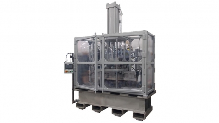
We were approached by an automotive customer who needed to crush (destructive test) their parts periodically to verify the integrity of the assembly. As the parts were part of a crush zone, with a certain amount of energy absorption required, they also needed to keep statistical data of the crush and trace it back to production runs.
After looking at various press manufacturers who specialize in this destructive testing, they found that they were struggling to get the performance they wanted at a price they were willing to pay. They approached us and said “hey you do hydraulics; can you help us with this”. We said “sure, this is in our wheel house, what do you really want.” This led to a discussion about forces, timing, and data acquisition.
Over a number of years, we co-developed and built a series of different size presses ranging from 50 tons (approx. 16” x 16” platen) to 90 ton presses (approx. 24” x 80”). Some frames the customer built and supplied, some frames we designed with Milwaukee Cylinder and supplied. Some were a single ram and some were dual ram with synchronized motion. One also included multiple high speed cameras which captured the crush visually as it occurred so that it could be compared to the crush forces. The crush data was overlaid on the video in real time.
The key to these presses was the Delta Motion controller. The Delta provided accurate and consistent velocity during the pressing sequence, as well as capturing the input from the load cell – monitoring tonnage. The data was then exported as an excel, xls file. This data we were then able to graph visually the results of the crush, as well as give a pass / fail criterion.
The final number of data points for a crush was typically in the 1000-2000 point range, at about .5mm increments every 1/10the of a second. We found that was a good place for efficiency and accuracy. But, it is capable of collecting data at the 1mS level, which at an average crush velocity of 2mm/s results in a data point every .002mm or just under 1/10th of a thousandth of an inch. At a standard crush distance of 120mm that comes out to 60,000 data points.
Along with the crush data, we captured the operator ID, date, time, and lot numbers of key sub assembly pieces. This info we then presented to the quality and engineering department as a single page PDF for their long term records. The raw data and video file we also pushed to their server for long term storage.
We are able to keep track of the extension of the press well into the 4th decimal place, as well as keeping track of forces +/- 90 lbs. on the 90-ton press.
If you need a custom solution for your application, the Donald Engineering team is here to assist you. Contact us today!
Show More...
Lenze Variable Frequency Drives to the Rescue
 In this application example the Donald Engineering team was assisting with a conveyer project which sorted the customer’s product for restacking or end of line repair. We were supplying the hydraulic and pneumatics while the Variable Frequency Drives (VFDs) solution that was provided by others was behind in delivery. The multiple VFDs started and stopped various sections of the conveyer smoothly. Product load on the conveyer varied from empty to as much as 400 lbs. per section. The original VFDs that were ordered from a competitor were going to put the entire project on hold for months.
But the Donald Engineering team had a solution and offered the Lenze drives.
The same afternoon Donald Engineering became aware of the need, our quote was approved with a Purchase Order to replace the original drives that were ordered. The delivery of the Lenze i550 IO Link drive was 4 weeks compared to months with the competitor.
The integrator stated that transition to the Lenze VFD was simple, quick to learn, and the cost savings was appreciated.
(Due to the competitive nature of the machinery we are unable to show photos or videos.)
This is a huge benefit of Lenze products. They maintain US stock on their i510 Protec series of VFDs, from 1/2hp to 7.5hp, and from single phase 120V to three phase 480V. And often have quick delivery on i550.
The stocked communication options include CANopen and Modbus RTU. There are three diagnostic modules available including a keypad, USB module and WiFi module. These options are available in stock to provide solutions for a variety of applications.
If you are in need of a NEW or replacement frequency drive, Contact our team to assist you with the right Lenze product and solution for your application!
Show More...
The Clippard Cordis Unit Can be the Heart of your Application
 Over the past few years Clippard has brought to us the Cordis family of precision, closed loop proportional air controls. Cordis means “of the heart”. This incredible valve is becoming the heart of many pneumatic control applications.
First they introduced proportional pressure control featuring both proportional fill as well as simultaneous bleed functionality. This provides much better pressure regulation than most proportional pressure offerings in the market at a great price.
Next they introduced a simpler proportional closed loop pressure control for dynamic applications at a better price point, featuring only a proportional fill circuit.
Now Clippard is introducing proportional, close loop FLOW control. See our featured article below!
In our customer’s case they have an application where their controlled process gas could not escape to the outside (into the environment) and they could not have ambient air from outside mix with their process gas.
There requirements were for two flow ranges from the same controller.
Both are very small flows of 6 sccm and 8.5 sccm. We were able to accomplish this with an accuracy of .06% in this application. To prove the integrity and purity of the process each assembly had to be leak tested. The parameters of the test were to fill each vessel to 150 psi and then close off and monitor for 24 hours. In the test time, we were given an allowable leak rate of less than 2 psi, or 1.2% of the total volume. Considering the volume was less than a ½ of a pint in volume, this represents a very low leak rate.
Clippard’s electronic critical flow controller for the win with incredible accuracy and integrity of build execution.
Unlike other mass flow controllers that require a 30-minute warm-up period, large differential pressures, limited flow ranges, the Cordis Flow Controller comes to life quickly and requires less than one-minute warm-up, Pressure drop is equal to or less than .5 psi, and flow ranges as low as 0 to 30 sccm. Higher ranges available.
We achieved precise, linear flow control within a closed-loop system with ultra-high resolution and repeatability.
The Clippard Cordis unit can be the heart of your application.
Contact us today if you have a unique application problem that the Donald Engineering team can assess and provide the right solution!
Show More...
Safety Saw Auto Cut-Off
 In recent history, we have had customers bring us some Auto Cut-Off saw applications. The following is an application overview of multiple applications condensed into one. Not all had exactly the same features and needs, but together they are merged and represented below.
This application was a repurposing on old pneumatically controlled circular saw heads into new production cut off saws.
The saw head featured a large diameter blade, pneumatic rapid up, rapid down – until just above the work piece, and then a controlled decent through the work piece by a rate control (think shock absorber). The blade – when raised retracted into a guard and eliminated access to the hazard of the blade teeth.
The machine sequence:
- Operator loaded the part by hand against the back stop through a light curtain protected load window
- Exited the protected space
- Pushed the go button to start the sequence
- Two part clamps closed and locked the part against the back stop
- Saw head rapid retracted (lowered) thru free space
- Saw head made contact with rate control and decelerated into cutting mode
- Saw head reached bottom of stroke and rapid returned up
- When saw up, blade stopped and clamps opened
- Ready for unload / load
For safety, we utilized a CM26 internally monitored safe return valve.
At any time while the saw was in motion, if the light curtain was broken, the CM26 redundant 5/2 safety valve would rapid return the saw blade up – cylinder fully extended to safe position and also drop out the current to the saw motor.
The valve was sized for flow / speed to return the saw head quickly. The light curtains were placed sufficiently far back for the reaction and travel time of the saw head.
For this application, DECI provided:
- CM26 Safe Return Valve
- Air Prep (FRL)
- Rate Control – down slow
- Rate Controls – fast up and fast down
- Saw Micro Mist lube system
- Part Clamp control valve
Customer integrated their own clamps, control PLC, safety relays, light curtain, mechanical build and perimeter guarding.
Contact us today if you have a unique problem that the Donald Engineering can assess and engineer the right solution!
Show More...
Safe Accumulator Systems for Pressure and Return Flow
 One of our customers had a challenging problem: Quickly move a large cylinder and briefly transmit a massive amount of energy in a safe (Cat 3 PLd), fast, and cost effective solution. Cost effective in purchase price and also operating costs.
The cylinder needed to extend 12+ inches and retract in less than a second while delivering tonnage throughout the extension stroke.
Along the process there were secondary issues that we addressed:
- System shock
- Electrical amp draw
- Footprint of power unit
Instead of a massive power unit with a large tank and 150 HP motor – with all its expense in electrical, we designed an accumulator system to store energy between cycles and a second accum system to deal with the extreme return tank surge flow.
 Four Main Features:
- Pressure Side Accumulators (see “A”)
- While the machine dwells, getting ready for the next cycle, we use the time to refill the pressure side accumulators.
- We now have a much smaller pump motor and tank that is running continuously versus a larger system being called on intermittently.
- Block and Stop (see “B”)
- Ross Stop and Block valve used to prevent any potential stored energy from going to a cylinder downstream when not desired.
- Lock out tag out procedures.
- Waiting for the accumulator dump valve to dump system
- Accumulator Dump Valve with manual dump and indication for stored energy (see “C”)
- Accumulator dump valve will dump accumulators at a controlled pace as to not create a huge inrush of oil into a tank.
- Dump valve has the following safety features:
- Since the pilot dump valve is not monitored or redundant, this valve cannot be relied on for full safety protecting.
- There is a pressure gauge or pressure transducer plumbed directly to the accumulators for visual indication of trapped stored energy.
- There is also a manual ball valve that can be used to dump the accumulator in case the pilot valve fails.
- Use of an accumulator to absorb a high rush of return line flow (see “D”)
- Accumulators are charged to a low pressure.
- As the inrush of oil comes into this assembly to the two smaller accumulators, the oil is forced up into the accumulator and energy absorbed.
- The oil is trapped from going back out via a check valve.
- The oil inside the accumulator is then discharged automatically through a flow control back to tank. Flow can be set to meet the flow restrictions of the return line filter.
We accepted the customer challenge to provide a safer, faster, and more cost effective solution.
1. We reduced the size of the power unit
2. We reduced the size and amp draw of the electrical system
3. We achieved a Cat. 3 PLd hydraulic safety rating
Our customer now has the ability to deal with massive return surge flow to the tank in a safe way.
Contact us today if you have a unique problem that Donald Engineering can assess and engineer the right solution!


